


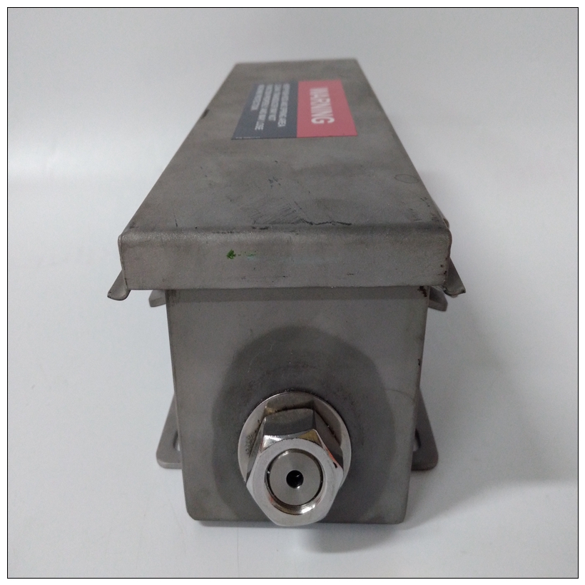

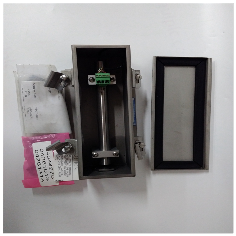
BENTLY 135613-02監測器模塊,135613-02使用參數
可以通過多種方式配置布線,以適應各種設備和系統配置。
圖1-23顯示了一種可能的配置。有關更多詳細信息有關安裝P2適配器板和的信息
MVME761過渡模塊,請參閱中列出的用戶手冊附錄D,相關文件。
7.更換機箱或系統護蓋,確保沒有電纜損壞擠壓。用電纜將外圍設備連接到面板連接器,然后重新連接將系統接至交流或直流電源,并轉動設備打開電源。
")
BENTLY 135613-02監測器模塊注:并非所有外圍電纜都隨MVME761提供。你可能需要制造或購買某些電纜。最小化輻射,摩托羅拉建議外圍設備使用屏蔽電纜盡可能連接。系統注意事項
MVME2700從VMEbus背板連接器P1供電和P2。P2還用于32位傳輸中的高16位數據,以及
對于擴展尋址模式中的上八個地址行。這個如果未連接主板,MVME2700可能無法正常工作至VMEbus背板連接器P1和P2。
MVME2700是作為VMEbus主機還是作為VMEbus運行從機,配置為32位地址和32位數據(A32/D32)。然而,它處理地址范圍內的A16或A24設備。D8和/或D16系統中的設備必須由PowerPC處理器處理軟件請參閱第2章操作說明中的內存映射。MVME2700包含共享板載DRAM和輔助緩存基址可由軟件選擇的存儲器。船上的兩個處理器和非車載VMEbus設備在基座上看到此本地DRAM物理地址$00000000,由固件編程。這可能是通過軟件更改為任何其他基址。請參閱MVME2600/2700系列單板計算機程序員有關更多信息,請參閱指南。如果MVME2700試圖以不存在的方式訪問非車載資源位置,并且不是系統控制器,如果系統沒有全局總線超時,MVME2700永遠等待VMEbus周期完成。這會導致系統鎖定。只有一種情況當系統可能缺少此全局總線超時時:當MVME2700不是系統控制器,并且在中的其他位置沒有全局總線超時系統。可以在單個VME機箱中安裝多個MVME2700。在里面一般支持硬件多處理器功能。VMEbus上的其他MPU可以中斷、禁用、與、,并確定處理器的操作狀態。一個GCSR(全局控制/狀態寄存器)集包括四個位,其功能如下位置監視器允許一個MVME2700處理器廣播信號
任何其他MVME2700處理器。所有八個寄存器都可以訪問來自任何本地處理器以及VMEbus。
Note The cabling can be configured in a number of ways to
accommodate various device and system configurations.
Figure 1-23 shows one possible configuration. For more detailed
information on installing the P2 adapter board and the
MVME761 transition module, refer to the user’s manual listed in
Appendix D, Related Documentation.
7. Replace the chassis or system cover(s), making sure no cables are
pinched. Cable the peripherals to the panel connectors, reconnect
the system to the AC or DC power source, and turn the equipment
power on.
Note Not all peripheral cables are provided with the MVME761. You
may need to fabricate or purchase certain cables. To minimize
radiation, Motorola recommends shielded cable for peripheral
connections where possible.System Considerations
The MVME2700 draws power from VMEbus backplane connectors P1
and P2. P2 is also used for the upper 16 bits of data in 32-bit transfers, and
for the upper eight address lines in extended addressing mode. The
MVME2700 may not function properly without its main board connected
to VMEbus backplane connectors P1 and P2.
Whether the MVME2700 operates as a VMEbus master or as a VMEbus
slave, it is configured for 32 bits of address and 32 bits of data (A32/D32).
However, it handles A16 or A24 devices in the address ranges. D8 and/or
D16 devices in the system must be handled by the PowerPC processor
software. Refer to the memory maps in Chapter 2, Operating Instructions.
The MVME2700 contains shared onboard DRAM and secondary cache
memory whose base address is software-selectable. Both the onboard
processor and offboard VMEbus devices see this local DRAM at base
physical address $00000000, as programmed by the firmware. This may be
changed via software to any other base address. Refer to the
MVME2600/2700 Series Single Board Computer Programmer’s
Reference Guide for more information.
If the MVME2700 tries to access offboard resources in a nonexistent
location and is not system controller, and if the system does not have a
global bus timeout, the MVME2700 waits forever for the VMEbus cycle
to complete. This causes the system to lock up. There is only one situation
when the system might lack this global bus timeout: when the MVME2700
is not the system controller and there is no global bus timeout elsewhere in
the system.
Multiple MVME2700s may be installed in a single VME chassis. In
general, hardware multiprocessor features are supported.
Other MPUs on the VMEbus can interrupt, disable, communicate with,
and determine the operational status of the processor(s). One register of the
GCSR (global control/status register) set includes four bits that function as
location monitors to allow one MVME2700 processor to broadcast a signal
to any other MVME2700 processors. All eight registers are accessible
from any local processor as well as from the VMEbus.