


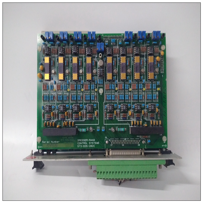
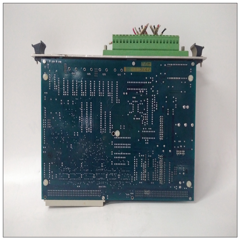
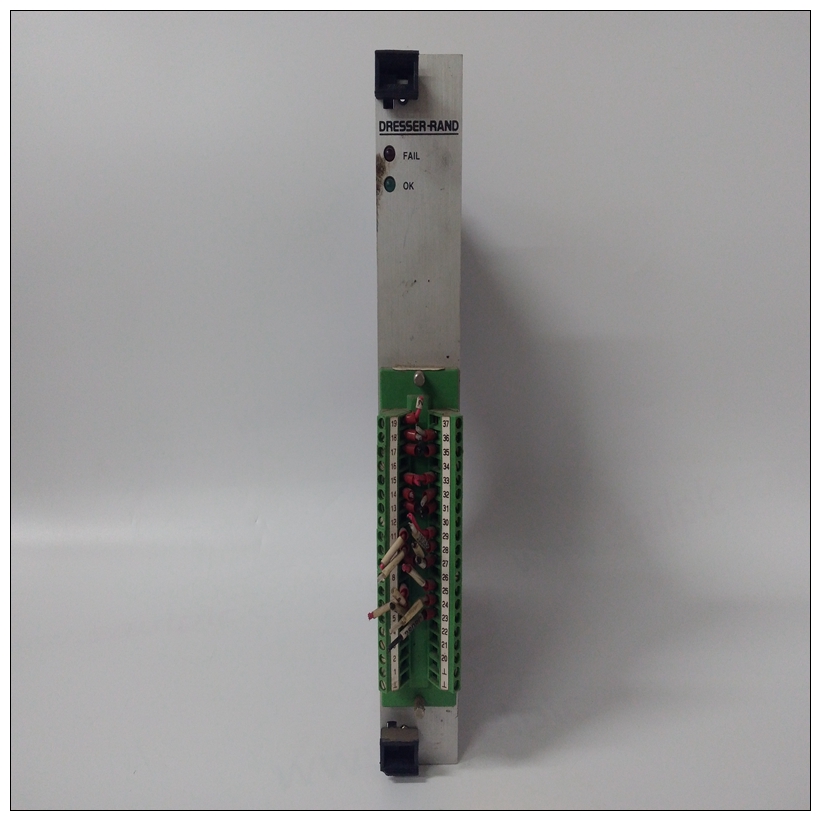
VIBRO 573-935-202C自動化模塊,使用區(qū)域
在MVME2603/2604基板上,標(biāo)準(zhǔn)串行控制臺端口(COM1)用作PPCBug調(diào)試器控制臺端口。固件控制臺應(yīng)設(shè)置如下:? 每個字符8位? 每個字符一個停止位? 禁用奇偶校驗(無奇偶校驗)? 波特率9600波特9600波特是MVME2603/2604上串行端口的通電默認值董事會。通電后,如果愿意,您可以重新配置波特率,通過命令行使用PPCBug PF(端口格式)命令界面無論波特率是多少,某種類型的硬件握手
")
VIBRO 573-935-202C自動化模塊-如果系統(tǒng)需要,則需要XON/OFF或通過RTS/CTS線路支持它。介紹本章提供了MVME2603/2604系列的使用信息系統(tǒng)配置中的單板計算機。在這里你會發(fā)現(xiàn)開關(guān)和LED的通電程序和說明,內(nèi)存映射和軟件初始化。施加功率在您驗證所有必要的硬件準(zhǔn)備已完成后已完成,所有連接均已正確完成,并且安裝完成后,您可以啟動系統(tǒng)。MPU,硬件和固件初始化過程由PowerPC PPCBug通電或系統(tǒng)重置。固件初始化SBC模塊上準(zhǔn)備啟動操作系統(tǒng)的設(shè)備系統(tǒng)固件出廠時附帶一套適當(dāng)?shù)哪J值。在大多數(shù)情況下,不需要修改固件啟動操作系統(tǒng)之前的配置。以下流程圖顯示了所需的基本初始化過程在PowerPC系統(tǒng)啟動期間放置。有關(guān)PPCBug的更多信息,請參閱第5章,PPCBug;到附錄C,CPU板故障排除:解決啟動問題;或附錄D中列出的PPCBug固件包用戶手冊,相關(guān)文件。MVME2603/2604前面板具有中止和重置開關(guān)以及六個LED(發(fā)光二極管)狀態(tài)指示器(CHS、BFL、CPU、PCI、FUS、,系統(tǒng))。開關(guān)和LED安裝在LED夾層板上插入基板
On the MVME2603/2604 base board, the standard serial console port
(COM1) serves as the PPCBug debugger console port. The firmware
console should be set up as follows:
? Eight bits per character
? One stop bit per character
? Parity disabled (no parity)
? Baud rate of 9600 baud9600 baud is the power-up default for serial ports on MVME2603/2604
boards. After power-up you can reconfigure the baud rate if you wish,
using the PPCBug PF (Port Format) command via the command line
interface. Whatever the baud rate, some type of hardware handshaking —
either XON/OFF or via the RTS/CTS line — is desirable if the system
supports it.Introduction
This chapter supplies information for use of the MVME2603/2604 family
of Single Board Computers in a system configuration. Here you will find
the power-up procedure and descriptions of the switches and LEDs,
memory maps, and software initialization.
Applying Power
After you have verified that all necessary hardware preparation has been
done, that all connections have been made correctly, and that the
installation is complete, you can power up the system. The MPU,
hardware, and firmware initialization process is performed by the
PowerPC PPCBug power-up or system reset. The firmware initializes the
devices on the SBC module in preparation for booting the operating
system.
The firmware is shipped from the factory with an appropriate set of
defaults. In most cases there is no need to modify the firmware
configuration before you boot the operating system.
The following flowchart shows the basic initialization process that takes
place during PowerPC system startup.
For further information on PPCBug, refer to Chapter 5, PPCBug; to
Appendix C, Troubleshooting CPU Boards: Solving Startup Problems; or
to the PPCBug Firmware Package User’s Manual, listed in Appendix D,
Related Documentation.The MVME2603/2604 front panel has ABORT and RESET switches and six
LED (light-emitting diode) status indicators (CHS, BFL, CPU, PCI, FUS,
SYS). The switches and LEDs are mounted on an LED mezzanine board
that plugs into the base board.