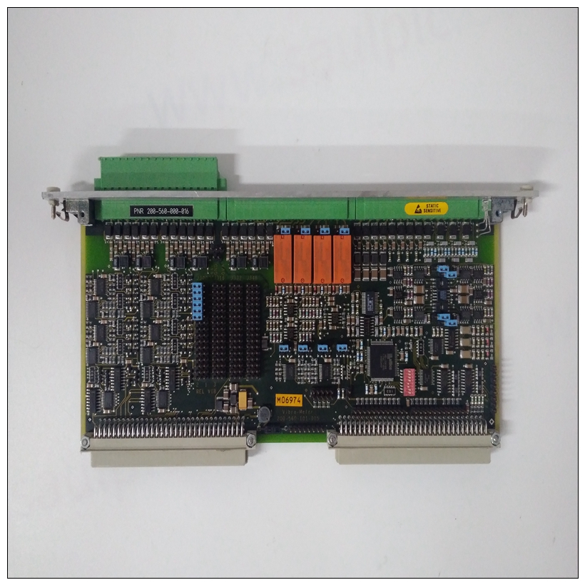
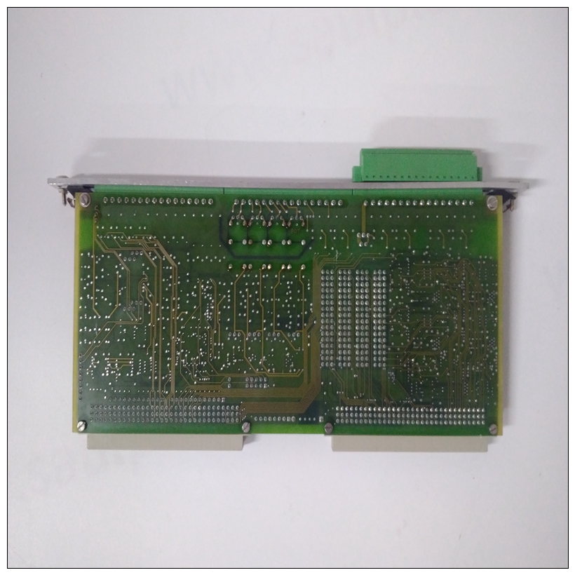
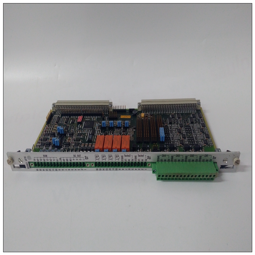
VIBRO 200-566-000-012卡件使用數據
MVME761過渡模塊安裝本節適用于MVME761兼容型號的MVME2603/2604 VME模塊。安裝MVME2603/2604后,參考圖1-22,按照以下步驟安裝MVME761
過渡模塊:1、將靜電帶系在手腕上。連接ESD的另一端
將皮帶系在底盤上作為接地。靜電放電帶必須固定在在整個過程中,您的手腕和地面。

VIBRO 200-566-000-012卡件使用數據2、執行操作系統關機。接通交流或直流電源斷開并從系統中卸下交流電源線或直流電源線。根據需要卸下機箱或系統蓋,以便訪問VME模塊MVME2600、MVME761兼容型號將在以下情況下損壞:錯誤地連接到MVME712系列板,而不是糾正MVME761過渡模塊。注:在MVME761兼容型號中,某些信號是通過P2多路復用以增加輸入/輸出容量。提到P2信號多路復用,詳見第3-15頁。在通電的情況下插入或拆卸模塊可能會導致損壞至模塊組件。
在這種情況下,存在可能導致死亡的危險電壓設備搬運、測試和調整時要格外小心。
機箱的前部或后部。(您可能需要將其他模塊移入機箱為MVME761的布線留出空間。)圖1-22。MVME761/MVME2603/2604電纜連接5.將配備MVME761的64芯電纜從P2適配器板上的J3到過渡模塊上的P2。確保用連接器針腳1.6定位電纜針腳1。用提供的螺釘將MVME761固定在機箱中,與橫向安裝軌道接觸良好,以將射頻發射。
注:可以通過多種方式配置布線,以適應各種設備和系統配置。圖1-22顯示了一種可能的配置。有關更多詳細信息有關安裝P2適配器板和的信息MVME761過渡模塊,請參閱用戶手冊(列出附錄D,相關文件)。
MVME761 Transition Module Installation
This section applies to MVME761-compatible models of the
MVME2603/2604 VME module. With the MVME2603/2604 installed,
refer to Figure 1-22 and proceed as follows to install an MVME761
transition module:
1. Attach an ESD strap to your wrist. Attach the other end of the ESD
strap to the chassis as a ground. The ESD strap must be secured to
your wrist and to ground throughout the procedure.
2. Perform an operating system shutdown. Turn the AC or DC power
off and remove the AC cord or DC power lines from the system.
Remove chassis or system cover(s) as necessary for access to the
VME modulesThe MVME2600, MVME761-compatible models will be damaged if
mistakenly connected to the MVME712 family of boards instead of the
correct MVME761 transition modules.
Note In MVME761-compatible models, certain signals are
multiplexed through P2 for additional I/O capacity. Refer to
P2 Signal Multiplexing on page 3-15 for details.Inserting or removing modules with power applied may result in damage
to module components.
!
Warning
Dangerous voltages, capable of causing death, are present in this
equipment. Use extreme caution when handling, testing, and adjusting.
3. Remove the filler panel(s) from the appropriate card slot(s) at the
front or rear of the chassis. (You may need to shift other modules in
the chassis to allow space for the cabling to the MVME761.)Figure 1-22. MVME761/MVME2603/2604 Cable Connections
5. Route the 64-conductor cable furnished with the MVME761 from
J3 on the P2 adapter board to P2 on the transition module. Be sure
to orient cable pin 1 with connector pin 1.6. Secure the MVME761 in the chassis with the screws provided,
making good contact with the transverse mounting rails to minimize
RF emissions.
Note The cabling can be configured in a number of ways to
accommodate various device and system configurations.
Figure 1-22 shows one possible configuration. For more detailed
information on installing the P2 adapter board and the
MVME761 transition module, refer to the user’s manual (listed
in Appendix D, Related Documentation).


