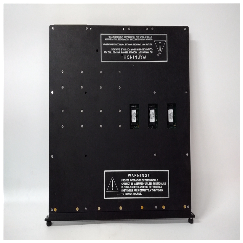
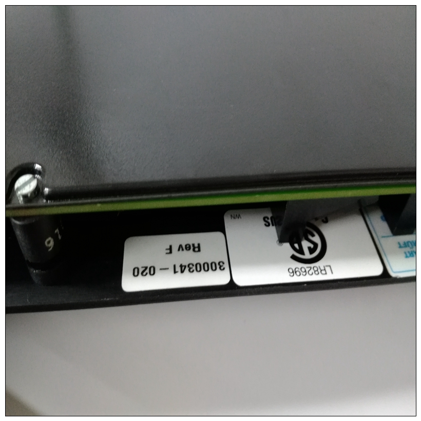
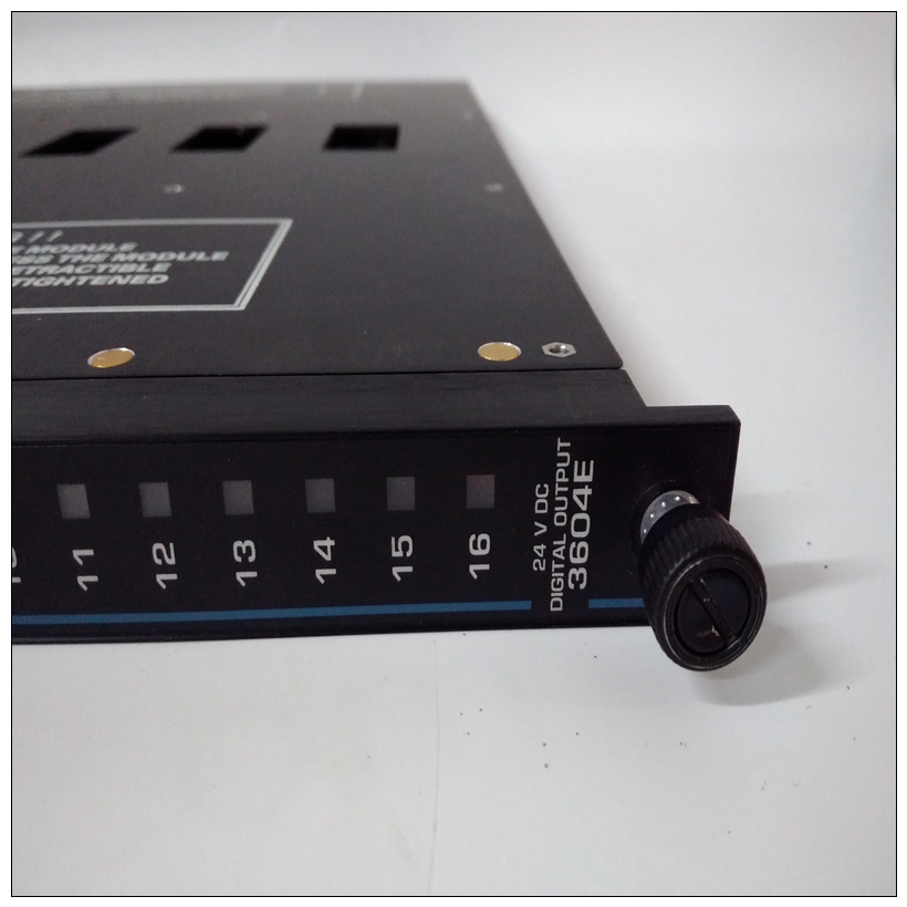
TRICONEX 3604E工控卡件,3604E實(shí)驗(yàn)數(shù)據(jù)
在機(jī)箱中安裝MVME187注意,如果要將MVME187用作系統(tǒng)控制器,它必須安裝在最左側(cè)的卡插槽(插槽1)中,否則可能安裝在任何未使用的雙高卡槽。
表3-9。MVME187安裝程序步進(jìn)動(dòng)作
1.將IACK和BG跳線從背板上拆下,用于安裝MVME187將安裝在中。
2小心地將MVME187滑入機(jī)箱前部的卡槽中。
? MVME187需要P1和P2供電。確保模塊正確安裝在背板。
? 不要損壞或彎曲連接器針腳。
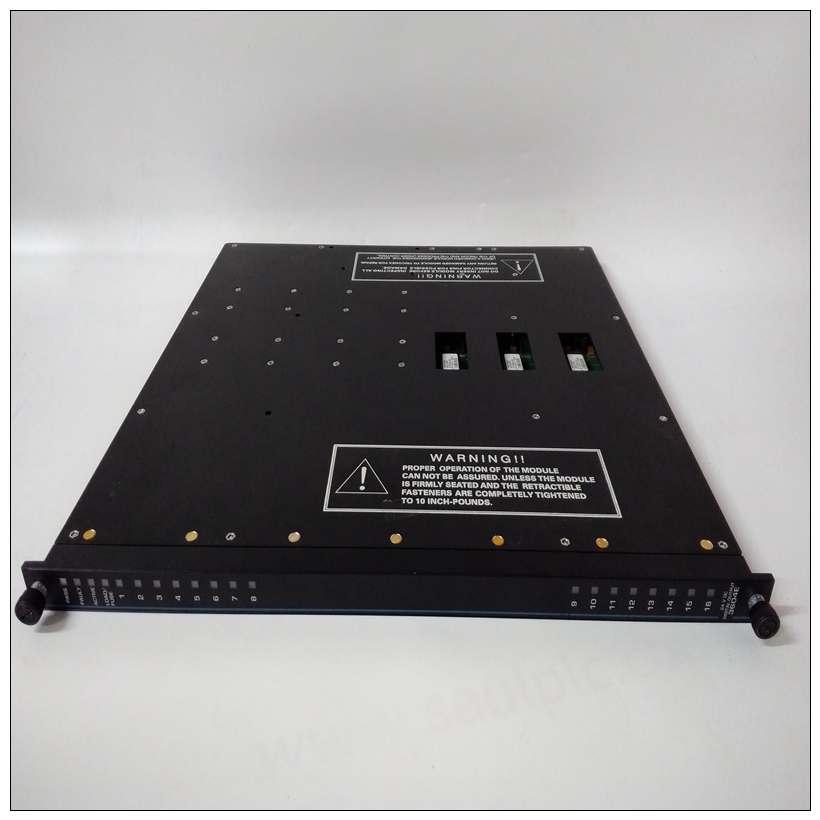
TRICONEX 3604E工控卡件? 用提供的螺釘將MVME187固定在機(jī)箱中,與橫向安裝軌道良好接觸,以盡量減少RFI排放。過渡模塊和適配器板概述MVME187支持MVME712-12、MVME712-13、,MVME712M、MVME712A、MVME712AM和MVME712B過渡模塊(本手冊(cè)中稱為MVME712X,除非另有規(guī)定)。注意:系統(tǒng)中的其他模塊可能必須移動(dòng)到為具有雙寬前面板的MVME712M留出空間。MVME712X轉(zhuǎn)換模塊提供配置頭和用于內(nèi)部和外部輸入/輸出設(shè)備的行業(yè)標(biāo)準(zhǔn)連接器。MVME187上的輸入/輸出連接到VMEbus P2連接器。
? MVME712X轉(zhuǎn)換模塊連接到MVME187直通電纜和P2適配器板,如圖所示在第3-18頁的圖3-2中。注:MVME712X未提供一些電纜因此必須由用戶。(摩托羅拉建議使用屏蔽電纜將所有與外圍設(shè)備的連接最小化輻射。)
Installing the MVME187 in the Chassis
Note that if the MVME187 is to be used as system controller, it must
installed in the left-most card slot (slot 1), otherwise it may be installed in
any unused double-height card slot.
Table 3-9. MVME187 Installation Procedure
Step Action
1 Remove IACK and BG jumpers from backplane for the card slot that the
MVME187 is to be installed in.
2 Carefully slide the MVME187 into the card slot in the front of the chassis.
? The MVME187 requires power from both P1 and P2. Be sure the
module is seated properly into the P1 and P2 connectors on the
backplane.
? Do not damage or bend connector pins.
? Fasten the MVME187 in the chassis with screws provided,
making good contact with the transverse mounting rails to
minimize RFI emissions. Transition Modules and Adapter Boards Overview
The MVME187 supports the MVME712-12, MVME712-13,
MVME712M, MVME712A, MVME712AM, and MVME712B
transition modules (referred to in this manual as MVME712X,
unless separately specified).
Note Other modules in the system may have to be moved to
allow space for the MVME712M which has a doublewide front panel.
MVME712X transition modules provide configuration headers and
industry-standard connectors for internal and external I/O devices.
The I/O on the MVME187 is connected to the VMEbus P2
connector.
? The MVME712X transition module is connected to the
MVME187 through cables and a P2 adapter board as shown
in Figure 3-2 on page 3-18.
Note Some cable(s) are not provided with the MVME712X
module(s), and therefore must be made or provided by
the user. (Motorola recommends using shielded cables
for all connections to peripherals to minimize
radiation.)


