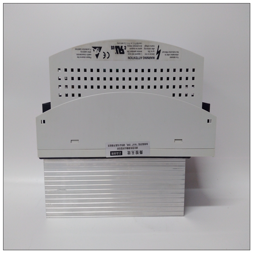
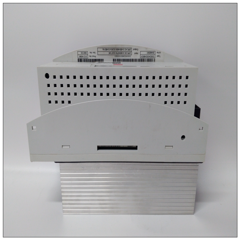
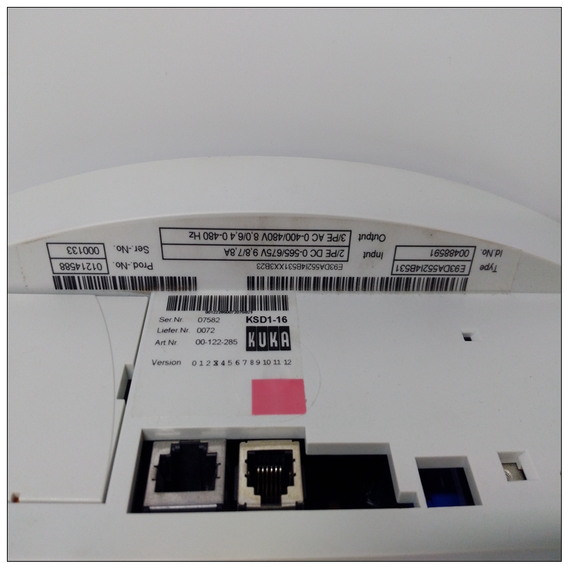
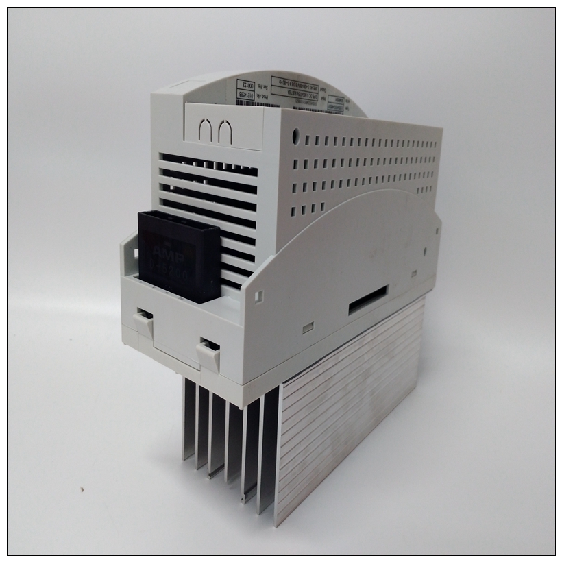
KUKA KSD1-16驅動器,KSD1-16使用指導
配置模塊數據區要配置模塊數據區域,請右鍵單擊硬件中的模塊節點配置,然后選擇配置。模塊的參數編輯器窗口出現。只讀參數的值由定義Profibus模塊的特性。大多數設備都有一個帶有輸入、輸出或二者都一些設備有多個數據區域,顯示為附加行。數據區參數區域該值是從1開始的索引。只讀。類型指定數據是輸入還是輸出,以及類型、數字或模擬。
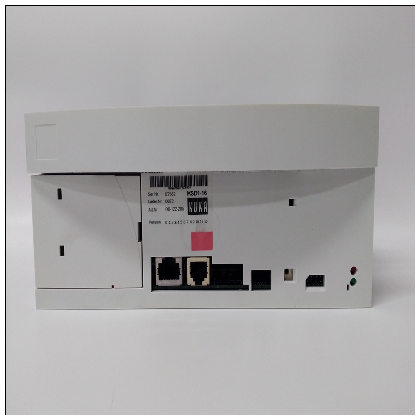
KUKA KSD1-16驅動器價值可以是數字的輸入、模擬輸入、數字輸出或模擬輸出。Ref Address指定用于映射數據區域的內存區域。不考慮引用類型使用時,輸入區域被視為已消耗且不能重疊,而輸出區域被視為已消耗視為已生產且可能重疊。允許范圍:%AI、%AQ、%I、%Q、%G、%R、%T、%M。如果字節數為奇數,則不允許使用模擬存儲器,并且選擇限制為:%I,%Q、 %G,%M長度指定引用的長度。默認情況下包括整個數據區域。如果設置為0,則數據未映射區域。允許的范圍:對于離散存儲器,允許范圍為[0,8,16,…,X]對于模擬存儲器,允許范圍為[0,1,2,…,X]交換字節交換字節字段用于操作字節順序。因為Profibus設備通常不會按照標準,提供了更改字節順序的能力。模擬區域進入如果需要LSB,則應交換MSB和。■ 如果類型為數字且模塊的字節數為奇數,則交換字節設置為False(否交換)和只讀。■ 如果類型為數字且模塊的字節數為偶數,則默認值設置為False。背景將字節交換為True會導致在將數據映射到之前交換LSB和MSBPLC存儲器。■ 如果類型為模擬,則默認值設置為False。將交換字節設置為True會導致LSB和在數據映射到PLC內存之前交換MSB。
Configuring Module Data Areas
To configure module data areas, right click the module node in the Hardware
Configuration, and choose Configure. The Parameter Editor window for the module
appears.
The values for read-only parameters are supplied from the GSD text file that defines the
Profibus module's characteristics. Most devices have one data area with inputs, outputs or
both. Some devices have multiple data areas that are shown as additional rows.
Data Area Parameters
Area
This value is an index beginning at 1. Read-only.
Type
Specifies whether the data is input or output as well as type, digital or analog. Value can be Digital
In, Analog In, Digital Out, or Analog Out.
Ref Address
Specifies the memory area that is used to map the data area. Regardless of the reference type
used, input areas are considered as consumed and cannot overlap, while output areas are
considered as produced and may overlap.
Allowable Ranges: %AI, %AQ, %I, %Q, %G, %R, %T, %M.
If the number of bytes is odd, analog memories are not allowed and selections are limited to: %I,
%Q, %G, %M
Length
Specifies the length of the reference. Includes the entire data area by default. If set to 0, the data
area is not mapped.
Allowable
Ranges:
For discrete memories, the allowable range is [0, 8, 16, …, X]
For analog memories, the allowable range is [0, 1, 2, …, X]
Swap Bytes
The swap bytes field is used to manipulate the byte order. Because Profibus devices often do not
follow the standard, the ability to change byte ordering is provided. The analog areas travel in
MSB and should be swapped if LSB is required.
■
If Type is Digital and the module has an odd number of bytes, Swap Bytes is set to False (no
swapping) and read-only.
■
If Type is Digital and the module has an even number of bytes, default is set to False. Setting
Swap Bytes to True causes the LSB and MSB to be swapped before the data is mapped into
PLC memory.
■
If Type is Analog, default is set to False. Setting Swap Bytes to True causes the LSB and
MSB to be swapped before the data is mapped into PLC memory.


