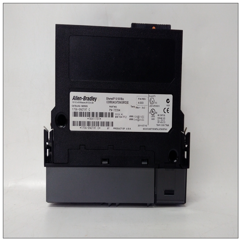
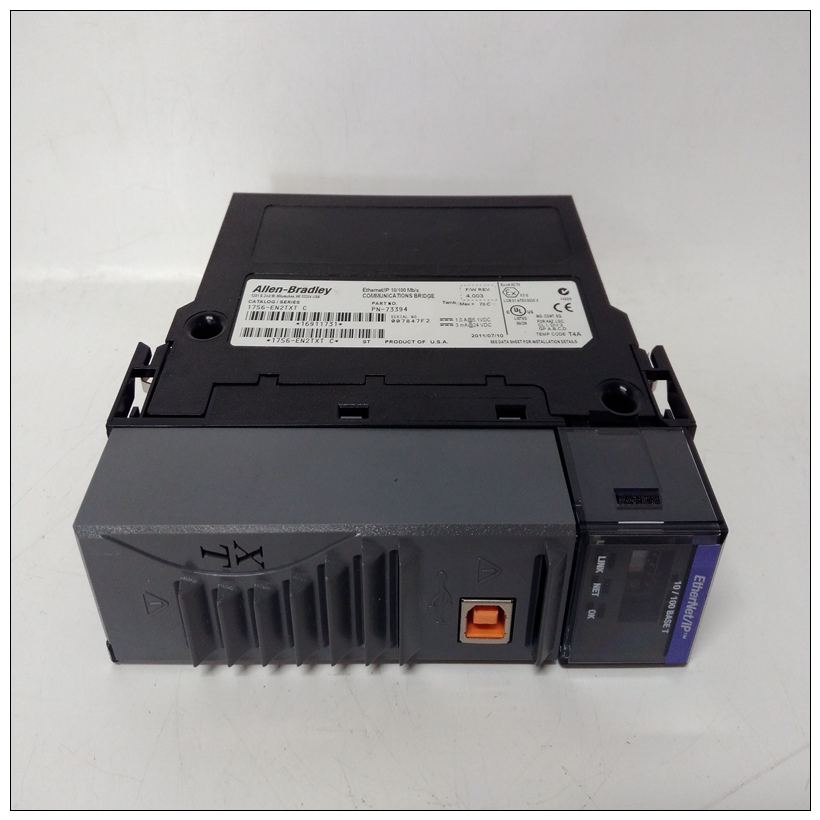
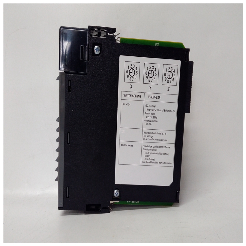
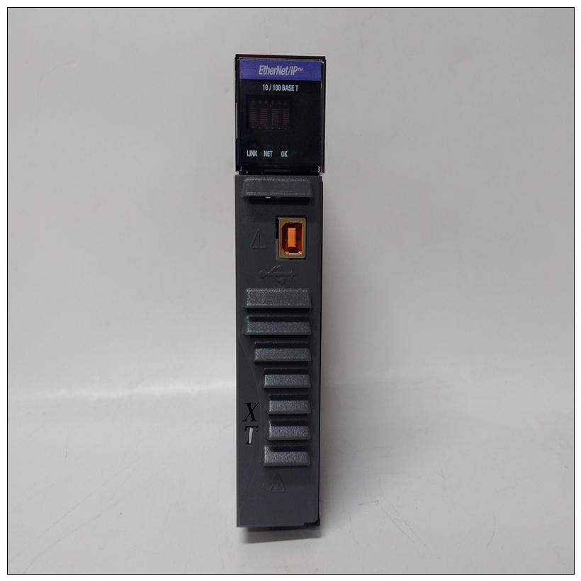
1756-EN2TXT模塊,1756-EN2TXT使用區域
NTDI01終端單元只能終止具有IMHSS02功能的HSS模塊。要安裝NTDI01終端裝置:參考TDI終端裝置產品說明書或附錄E選擇所需的雙工分流設置。
2.按照TDI產品說明中的步驟安裝現場終端面板的終端裝置。
3.將伺服閥、線性可變差動變壓器、數字I/O、24 VDC和I/O的接線連接至公用電路終端裝置。
4.按照TDI產品說明中的步驟進行連接將NKHS03電纜的J1連接到HSS模塊的MMU插槽。
將J2連接到終端裝置上的P1。綁好J3腿使其固定在一邊。

1756-EN2TXT模塊初始IMHSS03雙列直插式開關設置IMHSS03模塊有五個雙列直插式開關和31個跳線必須對其進行配置。雙列直插式開關設置適用依靠的本節中的信息涵蓋了開關初始安裝所需的設置。完成中的步驟本部分為模塊的安裝準備程序用于自動校準和調諧。
雙列直插式開關S1-輸入/輸出擴展器總線地址雙列直插式開關S1是一個八極雙列直插式開關。極點三通其中八個DIP開關設置輸入/輸出擴展器總線地址。極一個調用模塊診斷。有關diagnos雙列直插式開關設置,請參閱第6節。將HSS模塊輸入/輸出擴展器總線地址設置為任何未使用的地址二進制地址從零到63。雙列直插式開關極1和2必須處于關閉位置才能正常運行。使用電極3到8設置地址。表3-1列出了示例輸入/輸出擴展器總線地址雙列直插式開關設置。
The NTDI01 termination unit can terminate only an HSS mod�
ule having IMHSS02 functionality. To install the NTDI01 termi�
nation unit:
1. Refer to the TDI termination unit product instruction or
Appendix E to select the required dipshunt settings.
2. Follow the steps in the TDI product instruction to mount
the termination unit to the field termination panel.
3. Connect the wiring from the servo valve, linear variable dif�
ferential transformer, digital I/O, 24 VDC and I/O common to
the termination unit.
4. Follow the steps in the TDI product instruction to connect
J1 of the NKHS03 cable to the MMU slot for the HSS module.
Connect J2 to P1 on the termination unit. Tie wrap the J3 leg
of the NKHS03 cable so that it is secured out of the way.
INITIAL IMHSS03 DIPSWITCH SETTINGS
The IMHSS03 module has five dipswitches and 31 jumpers
that must be configured. Dipswitch settings are application
dependent. The information in this section covers the switch
settings needed for initial installation. Complete the steps in
this part of the installation procedure to prepare the module
for automatic calibration and tuning.
Dipswitch S1 - I/O Expander Bus Address
Dipswitch S1 is an eight-pole dipswitch. Poles three through
eight of this dipswitch set the I/O expander bus address. Pole
one invokes module diagnostics. Refer to Section 6 for diagnos�
tic dipswitch settings.
Set the HSS module I/O expander bus address to any unused
binary address from zero to 63. Dipswitch poles one and two
must be in the closed position for normal operation. Use poles
three through eight to set the address. Table 3-1 lists examples
of I/O expander bus address dipswitch settings. See Figure 3-1


