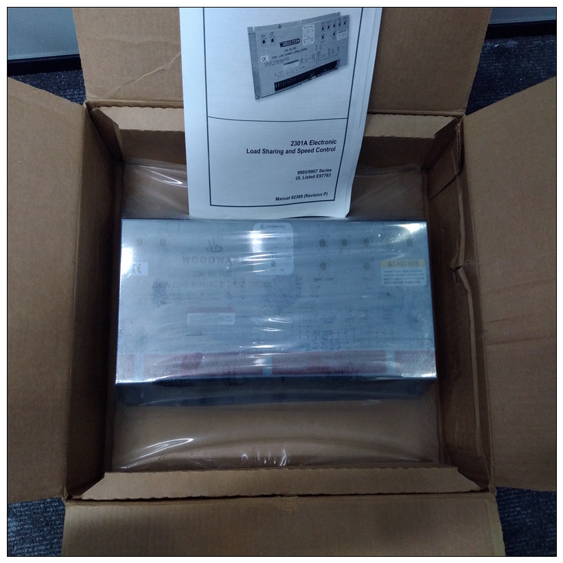
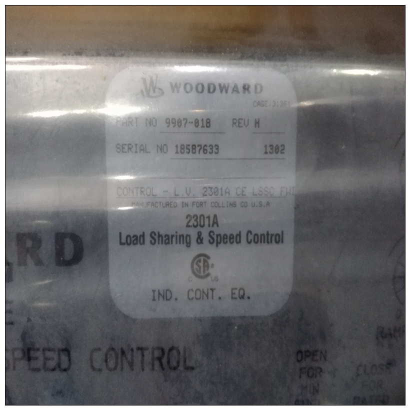
WOODWARD 9907-018調速器,9907-018使用配置手冊
將控制器板放回主板上,并用四個螺釘將其固定。現在原始傳感器信號位于連接條上。
安裝顯示器前,檢查插槽接線。
2、將A6110顯示器推入準備好的插槽,輕輕將其壓入插頭連接器。
3、用手擰緊前面板上的兩個固定螺釘,以固定顯示器。
任何其他信息,例如屏蔽和接地、監視器的配置等,都可以在“軸振動監視器A6110”的使用方向上找到,1.6技術數據

WOODWARD 9907-018調速器只有包含公差和極限值的信息才被視為綁定數據。數據無公差或誤差限值僅供參考。我們保留進行技術變化? 尤其是軟件。
如果沒有其他信息,則以下所有信息均適用于通道1和通道2明確規定。
1.6.1信號調節通道1和通道2的兩個獨立信號輸入,具有非耦合信號調節。
測量值輸入差分電壓放大輸入,非?無功,開路?電路和短路?電路驗證。
通道1 z8:SENS1H(+);z10:傳感器1L(? 信號)
通道2 d8:SENS2H(+);d10:傳感器2L(? 信號)
輸入標稱范圍?1,0 ... ?22.16伏限制范圍0。。。?30伏直流電
輸入電阻>100 kΩ
Place the controller board back on the main board and secure it with the four screws. Now,
the raw sensor signal is on the connection strip.
Installation
1. Check the slot wiring prior to installing the monitor.
2. Push the A6110 monitor into the prepared slot and press it with light pressure into the plug
connector.
3. Hand tighten the two anchoring screws on the front panel to secure the monitor.
Any other information, e. g. shielding and grounding, configuration of the monitor, etc., can be
found in the direction for use “Shaft Vibration Monitor A6110”, order number: 6110?90001.
1.6 Technical Data
Only information with tolerances and limit values are considered as binding data. Data without
tolerances or error limits are provided as information only. We reserve the right to make technical
changes ? particularly to the software.
All of the following information applies uniformly for channel 1 and channel 2, if not otherwise
specified.
1.6.1 Signal conditioning
Two separate signal inputs for channel 1 and channel 2 with uncoupled signal conditioning.
Measured value inputs
Differential voltage amplification inputs, non?reactive, open?circuit and short?circuit proof.
Channel 1 z8: SENS1H (+); z10: SENS1L (? Signal)
Channel 2 d8: SENS2H (+); d10: SENS2L (? Signal)
Input nominal range
?1,0 ... ?22.16 V
Limit range 0 ... ?30 V DC
Input resistance > 100 kΩ


