TRICONEX 4211系統卡件,TRICONEX 4211使用教程
要激活總線終端并將線路“A”和“B”放置在參考上,請插入跳線如圖b)所示。圖a)顯示了停用總線終端和斷開的跳線位置參考(交付狀態)。原始傳感器信號(未濾波,輸入?交直流變換器相位輸出信號部分)應用于前面板SMB插座,可在J2跳線接通的情況下切換端子z14:連接條的通道1和z16:通道2。
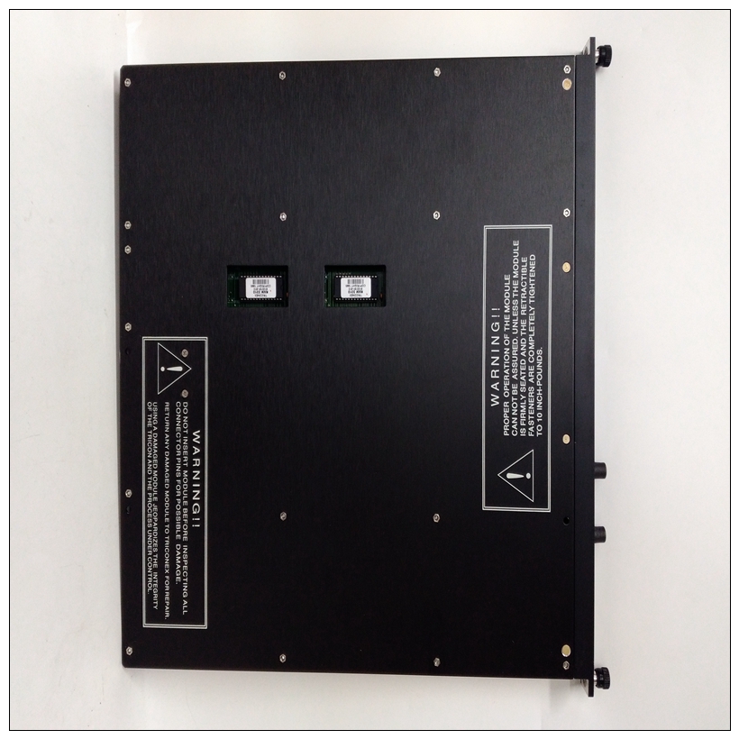
TRICONEX 4211系統卡件,交付時,J2跳線在端子z14和z16上設置傳感器信號的動態部分(縮放到輸出范圍0。。。20 Vss)應用。必須拆下控制器板才能切換信號在連接條上。使用十字頭螺絲刀拆下四個十字?有頭螺釘,標識為下圖中的箭頭。小心地將控制器板從主板上拔下,不要傾斜。J2的位置下圖中,主bard上的跳線用白色框架標識。要將原始傳感器信號切換到端子z14和z16,請按b)所示放置跳線。如果跳線設置如a)所示,則應用傳感器信號的動態部分在端子z14和z16上。
To activate the bus terminator and to place lines “A” and “B” on the references, plug the jumpers
as shown in Fig. b). Fig. a) shows the jumper position for deactivated bus termination and open
references (delivery status).The raw sensor signal (unfiltered, in?phase output signal of the converter with AC and DC
portion) applied to the front panel SMB sockets, can be switched over with the J2 jumpers on
terminals z14: channel 1 and z16: channel 2 of the connection strip. As delivered, the J2 jumpers
are set, that on terminals z14 and z16 the dynamic portion of the sensor signal (scaled to output
range 0 ... 20 Vss) is applied. The controller board must be removed in order to switch the signal
on the connection strip.Use a cross head screwdriver to remove the four cross?headed screws, identified with the
arrows, in the following figure.Carefully pull the controller board off the main board without tilting it. The position of the J2
jumpers on the main bard is identified with a white frame in the following figure.To switch the raw sensor signal to terminals z14 and z16 place the jumpers as shown in b).
If the jumpers are set as shown in a) then the dynamic portion of the sensor signal is applied
on terminals z14 and z16.


